Compass and IMU
The stock badge has no magnetometer, so every heading-up view falls back to GPS course over ground and only orients while you move. Fitting a TDK ICM-20948 on the SAO header J8 gives a tilt-compensated compass that holds standing still. It costs four wires, and J8 ships unpopulated, so nothing has to be desoldered.
This page covers the part and the wiring. The Compass app page covers the screen, the calibration sweep and what each state means.
The part sits on the SAO I2C bus at 0x68 or 0x69
Section titled “The part sits on the SAO I2C bus at 0x68 or 0x69”The ICM-20948 is a 3-axis accelerometer and gyroscope, plus an AK09916 magnetometer on a second die
inside the same package. Its I2C address is 0x68, or 0x69 when AD0 is tied high, so there is no
clash with the keyboard’s TCA8418 at 0x34. The bus runs at 400 kHz.
The magnetometer is not on this bus. It has its own fixed address, 0x0C, on a private bus behind the
ICM, and the driver reaches it through the ICM’s auxiliary I2C master: one channel (SLV4) for single
configuration transactions, another (SLV0) as a standing order that re-reads the nine data registers
on a schedule and leaves them in the ICM’s shadow registers, where a normal read collects them.
The alternative is bypass mode, which connects the magnetometer’s pins to the main bus so it looks like a second device. That path is a trap. It reads the identity and control registers perfectly, which makes it look correct, while returning measurements that are not fields. See Troubleshooting.
Only the accelerometer and the magnetometer produce the heading. The gyroscope and the die temperature are read but do not feed it, which is what makes the heading valid when the badge is still.
Four wires to J8
Section titled “Four wires to J8”| ICM-20948 | SAO pad | J8 pin | ESP32-S3 |
|---|---|---|---|
| VDD / VDDIO | 3V3 | 1 | - |
| GND | GND | 2 | - |
| SDA | SDA | 3 | GPIO4 |
| SCL | SCL | 4 | GPIO5 |
| INT, not used, leave open | GPIO2 | 6 | GPIO6, the default GPS TX pad |
| spare | GPIO1 | 5 | GPIO7 |
The firmware polls the sensor, so only power, SDA and SCL have to be connected. Leave INT and GPIO1 open: nothing in the firmware reads an IMU interrupt, and GPIO6 is where the GPS transmits by default, so wiring INT there would collide with it.
Watch the pin numbering. GPIO4 and GPIO5 are J8 pins 3 and 4, not 4 and 5. In the back view J8 pin 1 is the top of the rightmost column, so the I2C pair is the middle column with SDA above SCL. Landing one position out puts your SDA on GPIO7, which is the GPS receive pin.
Both expansion headers carry the 3.3 V rail only. There is no 5 V anywhere on J6 or J8, and the ESP32-S3 pins are not 5 V tolerant.
The breakout labels its I2C pins for SPI
Section titled “The breakout labels its I2C pins for SPI”This is the trap, and it is on the module rather than the badge. Cheap ICM-20948 breakouts, the WCMCU-20948 among them, label their header for SPI:
| Module pin | What it is in I2C mode | Goes to |
|---|---|---|
SCLK | the clock | SAO SCL, GPIO5 |
SDI | the data line | SAO SDA, GPIO4 |
NCS | selects I2C when high, usually pulled up on the module | leave open |
SDO | doubles as the AD0 address strap | leave open for 0x68, high for 0x69 |
VCC, GND | power | J8 pins 1 and 2 |
A module wired by those names to the pins the labels suggest answers at no address at all.
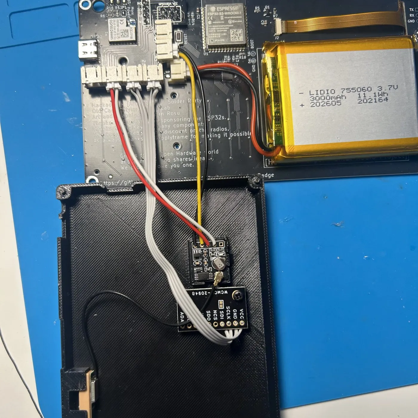
If nothing answers, the boot log says so and names the pins it tried, then scans the whole bus so a
part sitting at another address identifies itself. A WHO_AM_I of 0x00 or 0xFF means the bus is
not reaching the part at all rather than the wrong part being fitted. Most breakouts carry their own
4.7 kOhm pull-ups; the badge has none, and the ESP internal ones are around 45 kOhm, which is marginal
at 400 kHz with any wire length.
Mounting it inside the case
Section titled “Mounting it inside the case”J8 is a bare 2x3 through-hole footprint. Two routes keep the sensor inside the case:
- Solder the breakout straight to the J8 pads
- Fit a header there and use the internal addon board, whose I2C socket J4 carries SDA and SCL, with power from socket J2, J5 or J6
Keep it away from the speaker, the battery and anything ferrous. Whatever it ends up next to becomes part of the hard-iron offset that the calibration sweep measures, so moving the sensor afterwards means sweeping again.
What the firmware does with it
Section titled “What the firmware does with it”The driver in components/drivers/imu_icm20948.c is transport only: it identifies the part by its
WHO_AM_I byte, converts counts to g, degrees per second and uT at the finest full scales (2 g,
250 deg/s), and rotates the AK09916 axes into the accelerometer frame so the two dies can be fused.
The compass service in components/services/compass_svc.c owns the sampling task: it reads at 20 Hz,
applies the saved magnetometer correction, computes a tilt-compensated heading, adds the declination,
and publishes one smoothed heading that the map-style apps read.
Nothing starts unless imu_enabled is on, and that setting is read once at boot, so enabling the
compass or moving its pins needs a restart. With it off, or with no part answering, the service logs
one line and the badge boots normally.
No heading is published at all until the magnetometer is calibrated, because an uncorrected one can be tens of degrees out. The sweep lives in the Compass app, and the result goes into its own NVS blob, so it survives reboots and applies to the next sample.
Settings
Section titled “Settings”| Setting | Key | Type | Default |
|---|---|---|---|
| IMU compass enabled | imu_enabled | bool | on |
| Compass SDA pin | imu_sda_pin | int, 0 to 48 | 4 |
| Compass SCL pin | imu_scl_pin | int, 0 to 48 | 5 |
| I2C address 0x69 (AD0 high) | imu_addr_hi | bool | off |
| Declination (0.1 deg, E+) | mag_decl_ddeg | int, tenths of a degree, -1800 to 1800 | 0 |
| Use saved calibration | mag_cal_use | bool | on |
The bus pins are settings, so the sensor does not have to be on the SAO pair: wire it wherever two
pins are free and set them to match. imu_addr_hi covers a board that straps AD0 high, which
otherwise looks exactly like a sensor that is not there.
mag_decl_ddeg and mag_cal_use are re-read about once a second, so they take effect while the badge
runs. The other four need a restart.
Declination is yours to set, because the badge carries no magnetic model
Section titled “Declination is yours to set, because the badge carries no magnetic model”The firmware cannot derive the local angle between magnetic and true north from your position, so you
enter it. Look it up for where you are, east positive, in tenths of a degree: 2.4 degrees east is
24, and 8.0 degrees west is -80.
Every bearing the firmware shows is true north, which is what makes this matter. Get it wrong and every heading is out by the same fixed amount, while distances and bearings between two positions stay correct. The Diagnostics Heading row prints the true heading, the magnetic heading and the declination together for exactly that check.
Which views use it
Section titled “Which views use it”Once the compass is calibrated and fresh, Tracker, Follow and the Nodes row needles take their heading from it with no toggle to set. Radar and Map default to north-up and consult it once F1 selects heading-up. GPS course over ground stays the fallback while you move faster than 1 knot, and those views revert to north-up when neither source is usable, naming which of the four reasons applies: no compass, nothing calibrated, a calibration switched off, or no sample yet.
What has been verified
Section titled “What has been verified”An ICM-20948 on this bus is detected and identified on hardware: WHO_AM_I reads 0xEA, and the
AK09916 answers over the auxiliary master, accepts a soft reset, enters continuous mode and streams
into the shadow registers. That exercises the register map, the user-bank switching, both aux channels
and the self-test against the real part. The accelerometer reads a steady 1.0 g, so roll and pitch are
good.
A second magnetometer is being evaluated because of that, since the AK09916 has no oversampling control and therefore no way to filter a disturbance faster than its sample rate. See Magnetometer options for the candidates, the identification traps on the cheap boards, and why the ICM stays fitted for its accelerometer either way.
The magnetometer is not yet trustworthy on the test badge. Readings carry roughly 200 to 400 uT of spread on every axis when the part is stationary, against an earth field of 25 to 65 uT, so the firmware suppresses the heading rather than publishing a bearing derived from it. Eliminated by measurement so far: the access path, the bus speed, the aux master’s poll rate, byte order, the register map, read synchronisation, backlight interference, and the calibration and heading maths. The spread varies with sample rate, which points at a high-frequency disturbance being aliased into the samples rather than at the part. Three modules from two suppliers behave the same way.
The heading has therefore never been checked against a known bearing, and the axis transform between the two dies is untested in the field. Read the heading against a bearing you trust before relying on it.