Communicator Badge firmware
This firmware replaces the stock lvgl_micropython build on the Hackaday Supercon 2025
Communicator badge. It is written in C against ESP-IDF, and it turns the badge into a working
Meshtastic node: text messages over LoRa with other badges, stock Meshtastic devices, and the
Meshtastic phone app. The on-air format is the real Meshtastic wire protocol, so packets
interoperate.
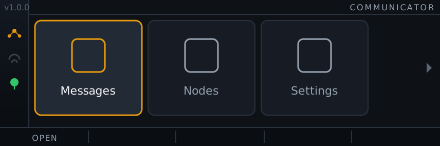
Every screen shares that chrome: a status sidebar that stops where the function-key bar begins, a right-aligned title, and five keys whose labels name what the next press does. The renders on these pages are drawn from the firmware’s own layout constants and colour tokens, so the geometry matches the panel exactly.
Twelve apps on the badge itself
Section titled “Twelve apps on the badge itself”Twelve apps sit behind a scrolling launcher. Messages runs several channels at once. Nodes, Tracker, Follow, Radar, and Map place other people by range and bearing, over an offline vector map you build yourself. Breadcrumbs logs your own track to flash. Settings, Diagnostics, GPS, and Compass expose the state of every subsystem. With WiFi on, a web UI configures the badge, backs up its settings, and flashes firmware over the air.
The interface uses one font, a single amber accent on a dark background, and monochrome icons. A status sidebar runs down the left edge and a function-key bar spans the bottom.
Peripherals are interrupt driven: the keyboard and radio wake the CPU on demand instead of the busy-poll loops the MicroPython build needed, and the CPU scales its frequency to save power.
The hardware it needs
Section titled “The hardware it needs”A stock badge is enough for messaging and the whole UI. Three optional parts, all enabled by default in Settings, add the position and heading features:
| Part | Where it connects | What it adds |
|---|---|---|
| Stock badge (required) | ESP32-S3, NV3007 428x142 TFT, SX1262 LoRa, TCA8418 keyboard | Messaging, the launcher, the whole interface |
| ATGM336H GPS | SAO spare GPIO, ESP GPIO7 in and GPIO6 out | Position, speed, breadcrumb tracks, radar range and bearing |
| TDK ICM-20948 | SAO I2C on header J8, GPIO4 and GPIO5 | A tilt-compensated heading that holds while you stand still |
| Vibration motor | One GPIO, GPIO12 (J6 IO12) by default | A buzz on an incoming message |
Every pin above is a setting, so a different wiring only needs a value changed, not a rebuild.
The compass code has not yet run against a real ICM-20948: on the test badge nothing acknowledged on the I2C bus, a wiring fault on that unit. Its portable maths is covered by 388 host-test checks, but the heading output on silicon is unproven. Without a compass fitted the heading-up views fall back to GPS course over ground, which only works while you are moving.
Where to go next
Section titled “Where to go next”Install the toolchain on the Install ESP-IDF page, then build and flash the firmware and work through first boot.
To change the firmware, start with the architecture overview for the layering and the task list, then the conventions. The protocol, navigation, and layout logic is covered by a host test suite that runs on a PC with no hardware.
For the pinout and the optional parts, see Board and pins.