Architecture overview
Logic that can be tested on a PC lives in a portable component, and everything else layers on top of it. The lower layers hold no ESP-IDF, LVGL, or FreeRTOS includes, so the protocol, crypto, compass, and layout code compiles into the firmware and into the host test suite from the same source files. That is the rule to check a change against before anything else.
Components
Section titled “Components”main/ app_main.c boot sequence, board_pins.h, app_config.h (bsp)components/ core/ portable event bus, schema settings (plus NVS store), node DB mesh/ portable AES, Meshtastic crypto, packet, regions, nanopb protobufs util/ portable NMEA parser, geo, radar/map projection, vmap reader, compass maths (heading, calibration, arbitration) net/ portable message types, dedup, router, Meshtastic backend drivers/ esp-idf NV3007 display, TCA8418 keyboard, SX1262 radio, GPS UART, ICM-20948 IMU, vibration motor, battery, power radio/ esp-idf radio task: receive ISR to parse, transmit queue, listen-before-talk services/esp-idf status sidebar, mesh beacon, time from GPS, battery, GPS, compass, vibration, breadcrumb track, WiFi, web UI, OTA ble/ esp-idf NimBLE advertising and the Meshtastic BLE service ui/ lvgl theme, frame, sidebar, bottom bar, launcher strip, map canvas, icons apps/ lvgl launcher plus the 12 registered appscore, mesh, util, and the portable parts of net and ui register their CMake
components with no IDF dependency. host_tests/ compiles those same files with zig cc.
The 12 apps register in app_manager.c: Messages, Nodes, Settings, Diag, GPS, Bread-crumbs,
Follow, Packets, Tracker, Radar, Map, Compass. launcher.c caps the tile strip at
TILE_MAX 16, deliberately above the app count: a cap below it silently drops the tail of the
list off the home screen, which is how Radar and Map became unreachable at 8 tiles.
The firmware creates nine FreeRTOS tasks of its own. Three are conditional: gps needs
gps_enabled, radio needs the SX1262 to initialise, and compass needs imu_enabled plus an
IMU that answers on the bus. Stacks are in bytes; ui and the flash-writing paths need internal
RAM, which is the scarce resource on this board. ESP-IDF and NimBLE add their own tasks on top
when WiFi or BLE is enabled.
| Task | Owns | Wakes on | Stack | Core |
|---|---|---|---|---|
ui | LVGL, the apps, the launcher, input dispatch | the next LVGL timer | 8192 | 1 |
radio | the SX1262 receive, transmit, and CAD state machine | the DIO1 interrupt | 4096 | 0 |
kbd | TCA8418 decode, function key and modifier state | the keyboard interrupt semaphore | 3072 | 0 |
gps | NMEA reads from the GPS UART, the current fix | UART bytes, 200 ms read timeout | 3072 | 1 |
compass | ICM-20948 reads, tilt-compensated heading, the calibration sweep | a 50 ms delay (20 Hz) | 3072 | 1 |
track | the breadcrumb file on SPIFFS and the recent-trail ring | a 5 s delay | 4096 | 1 |
mesh_svc | node info and position beacons | a 5 s delay | 4096 | 0 |
time | the system clock, set once from a GPS fix | a 10 s delay | 2560 | 1 |
bl | the backlight dim and off policy | a 1 s delay | 2560 | 1 |
The compass task only exists when imu_enabled is on and the IMU answers at boot. The
compass service publishes one heading snapshot that the apps copy out from the UI task, the
same way they read a GPS fix, plus one status snapshot carrying the derived state, so the
Compass page, Diagnostics, and every heading-up view report the same cause when there is no
heading. Its stack matches the GPS task at 3072 bytes.
The vibration service has no task. It registers its settings, starts the driver, and
subscribes to EV_MESSAGE_RECEIVED; the handler arms an esp_timer one-shot that drops the
motor pin again, so it runs on the radio receive stack and returns immediately.
Event bus and threading
Section titled “Event bus and threading”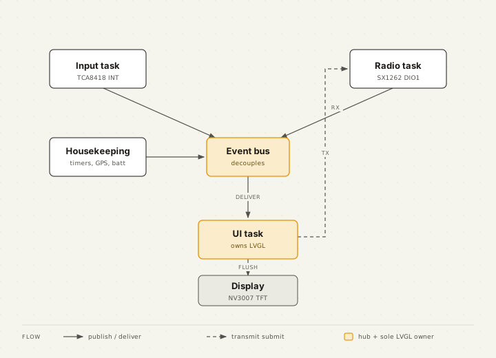
A small synchronous event bus carries events such as EV_MESSAGE_RECEIVED and
EV_MESH_NODE_UPDATE. Handlers run on the publisher’s stack, so they stay short and never
call LVGL.
LVGL is single threaded and only the ui task touches it. The radio task publishes received
messages into a queue, and the apps drain that queue on their own timer inside the UI task.
Every LVGL call then happens on one thread.
Boot sequence
Section titled “Boot sequence”app_main() builds the system bottom up, so nothing is started before what it depends on:
- NVS, the node identity derived from the efuse MAC, and the settings registry (radio and
power schemas), then
ble_prepare()to reclaim the Bluetooth controller RAM when BLE is off - Display, theme, backlight, and the persistent chrome (sidebar and bottom bar)
- Keyboard
- Network config and the radio task
- Services, each registering its own settings and starting its own task or timer: battery, GPS, compass, time, mesh beacon, track, WiFi, vibration, BLE
- Apps: Messages, Radar, and Settings state, then the app manager and the status service
- Power policy (dynamic frequency scaling, backlight dim and off)
- The UI task, last, so every LVGL object was built single-threaded before it runs
ota_mark_valid() then confirms the image, which is how a pending OTA slot is kept.
Settings registry
Section titled “Settings registry”53 settings register across 14 groups: Radio, Channels, Device, Network, WiFi, Bluetooth, GPS,
Compass, Vibration, LED, Battery, Power, Messages, Radar. The registry array is fixed at
SETTINGS_MAX 64, so a new schema needs no allocation, but adding more than 11 further settings
does need that constant raised. Registration order decides the order the groups appear in, both on
the badge and in the web form, so it follows the boot sequence rather than the alphabet.
Each service owns its own schema, registered in the service’s *_svc_init(). A setting is
therefore only present if the code that reads it was compiled in.
What is proven and what is not
Section titled “What is proven and what is not”The firmware builds clean for esp32s3, the host suite passes at 1113 checks with 0 failures,
and a flashed badge boots with the GPS, the vibration motor and the notification LED coming up on
their pins.
The compass transport is confirmed against a real ICM-20948: the part is detected, WHO_AM_I reads
0xEA, and the AK09916 on the second die answers and enters continuous mode, which exercises the
register map, the user-bank switching and the ICM’s auxiliary I2C master path. Above that layer nothing is proven. No
heading has been compared against a known bearing, and the axis mapping between the two dies and the
calibration flow are untested in the field. The portable maths under them carries 388 host checks,
which is a claim about the maths and not about the sensor.