
Hardware and variants
Four boards wear the same cube. Confirm which one you have before you flash it, because they use different chips and flash differently. The screen is the same 1.54” 240×240 ST7789 IPS panel on all of them.
The GeekMagic SmallTV is a 45 × 35 × 40 mm cube with a 28 × 28 mm colour screen and a USB-C port for power. It sells for about 6 to 8 EUR on AliExpress. A second version of the hardware, sold under the same “smart weather clock” listing, swaps the ESP8266 for an ESP32-C2 but keeps the case and screen. A third device, the NMMiner NM-TV-154 BTC lottery miner, uses the same cube and screen with a classic ESP32 inside. And GeekMagic’s own upmarket model, the SmallTV Pro, pairs a classic ESP32 with 8 MB of flash.
Tell them apart
Section titled “Tell them apart”Look at the board through the case vents, or open it (four clips, no glue).
- SmallTV (ESP8266): an ESP8266 module, no separate USB-serial chip. Flashes over the air.
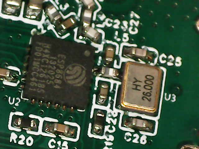
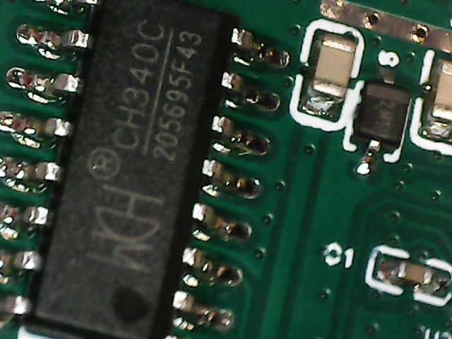
- SmallTV (ESP32-C2): a bare ESP8684 chip (that is the ESP32-C2) plus a CH340C USB-serial chip next to the USB-C port. Flashes over USB-C.
- NM-TV-154 (ESP32): the PCB reads NM-TV-Miner and carries an ESP32-WROOM-32E module. Sold as an NMMiner BTC lottery miner, not as a weather clock. Flashes over USB.
- SmallTV Pro (ESP32): sold by GeekMagic as the SmallTV Pro, with a capacitive touch button on top of the case. A classic ESP32 with 8 MB flash. The USB-C port is power only (no USB-serial chip): flashes over the air from the stock web UI, or over an internal UART header.
The two chips on the ESP32-C2 board are the giveaway. The main SoC is marked ESP8684, and the small 16-pin chip by the USB-C port is the CH340C.
SmallTV (ESP8266)
Section titled “SmallTV (ESP8266)”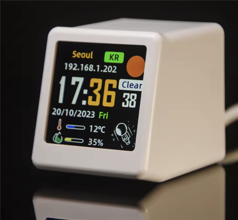
The “Ultra” units (branded Ultra-Vx.x.x) are this same ESP-12F board, just with different stock firmware and a different flash layout. They run this firmware fine, but the first install needs the loader step in Flashing.
Product photos show each unit running its stock firmware, not this one, and the on-screen style varies by model and firmware version (a weather clock, a ticker, and so on). Match your device’s screen and the tell-tale signs to identify the model before picking a binary.
| MCU | ESP-12F (ESP8266), 4 MB flash |
| Display | 1.54” 240×240 IPS ST7789, hardware SPI |
| Body | 45 × 35 × 40 mm, USB-C power |
| Light sensor | optional LDR on A0 (not populated on all units) |
| WireGuard VPN | not available on this chip |
| Build env | smalltv, or smalltv_lean |
Two images are published for this board. smalltv-mod-firmware.bin carries every feature. smalltv-mod-firmware-lean.bin is the same code with Home Assistant screens and the usage meter compiled out, which leaves the heap 8,732 bytes larger. That matters here and on no other board, because the ESP8266 shares one 80 KB arena between static allocations and the heap, and the radar and cash.ch fetches both refuse to start a TLS handshake when it runs short. Which release file to download covers when to pick which.
Pin map
Section titled “Pin map”Hardware SPI on the ESP8266 uses fixed clock and data pins. The rest are the SmallTV wiring, confirmed from teardowns and the ESPHome and Tasmota communities.
| Signal | GPIO | Note |
|---|---|---|
| SPI CLK | 14 | hardware SPI (fixed) |
| SPI MOSI | 13 | hardware SPI (fixed) |
| DC | 0 | boot-strap pin |
| RST | 2 | boot-strap pin |
| CS | 15 | boot-strap pin |
| Backlight | 5 | PWM, active-low |
SmallTV (ESP32-C2 / ESP8684)
Section titled “SmallTV (ESP32-C2 / ESP8684)”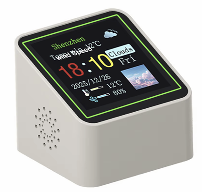
| MCU | ESP32-C2 (ESP8684), 4 MB embedded flash, RISC-V, 120 MHz |
| USB-serial | CH340C on the USB-C port (auto-reset wired) |
| Regulator | AMS1117-3.3 |
| Display | 1.54” 240×240 IPS ST7789V, SPI, RGB colour order |
| WireGuard VPN | included |
| Build env | smalltv_c2 |
The ESP32-C2 has no native USB. The CH340C bridges the USB-C port to the chip’s UART, which is how it is flashed. Its auto-reset is wired, so esptool enters download mode on its own with no button to hold.
Pin map
Section titled “Pin map”The ESP32-C2 routes SPI through the GPIO matrix, so the display pins are arbitrary GPIOs rather than fixed hardware-SPI pins. This map comes from a community ESPHome config for this exact board and is confirmed working.
| Signal | GPIO | Note |
|---|---|---|
| SPI CLK | 4 | |
| SPI MOSI | 6 | |
| DC | 5 | |
| RST | 1 | |
| CS | GND | tied low on the panel, not driven |
| Backlight | 18 | PWM, active-low |
The pins are set in src/board_esp32c2.h. Two panel quirks are worth knowing: the display needs SPI mode 3, and its colour order is RGB. Both are handled in src/Gfx.cpp. If red and blue look swapped on your unit, set “Colour order” to BGR in the Display tab; the board header’s TFT_BGR is only the default the web UI starts from.
NM-TV-154 (classic ESP32)
Section titled “NM-TV-154 (classic ESP32)”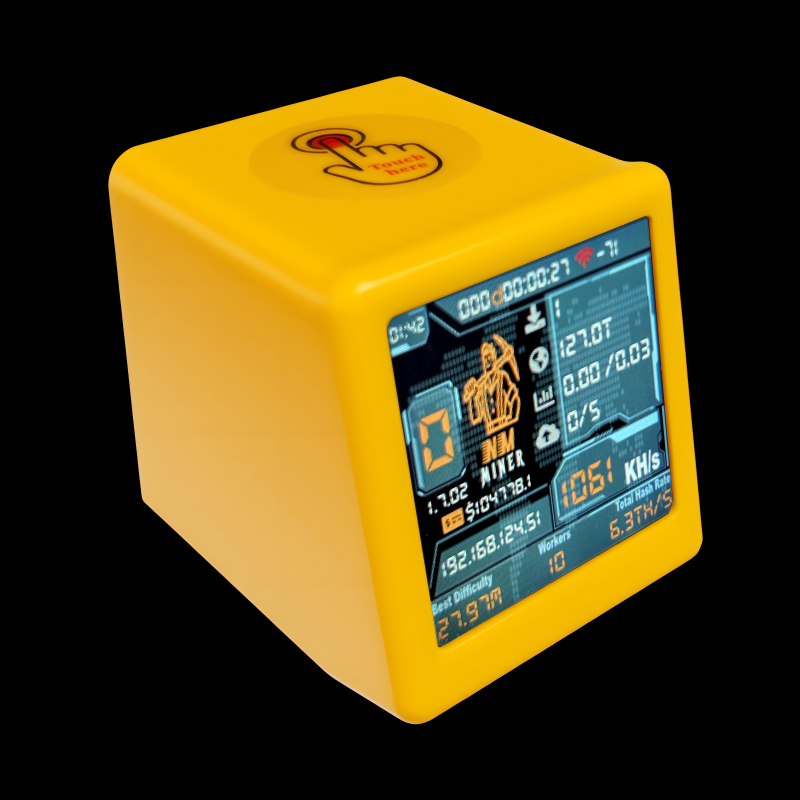
| MCU | ESP32-WROOM-32E (ESP32-D0WD-V3), 40 MHz crystal, 4 MB flash |
| Display | 1.54” 240×240 IPS ST7789, SPI, RGB colour order |
| Sold as | NMMiner NM-TV-154 BTC lottery miner, PCB marked “NM-TV-Miner” |
| WireGuard VPN | in the second image only, -esp32-wg |
| Build env | smalltv_esp32, or smalltv_esp32_wg |
Two images are published for this board, and the only difference is the WireGuard client. smalltv-mod-firmware-esp32.bin leaves it out; smalltv-mod-firmware-esp32-wg.bin compiles it in. Both carry every other feature, run the same code and use the same partition table.
The split exists because of flash. The 4 MB layout gives each OTA slot 1,572,864 bytes, and the classic ESP32’s own framework libraries cost about 100 KB more than the ESP32-C2’s. The published images measure 1,422,042 bytes (90.4%) without the client and 1,467,670 bytes (93.3%) with it, so the tunnel costs 45,628 bytes and leaves 105,194 free. Both fit comfortably. It is still a choice because the slot cannot be grown without a new partition table, and a device in the field cannot install one over the air, so the room the plain image keeps is the only room this board will ever have for whatever the firmware grows into next, and the tunnel spends about a third of it.
Take -esp32-wg if you want to reach the device from outside your LAN. Take the plain one otherwise. Swapping later is a manual upload in the System tab and needs no cable, because the two images share a partition table; Which release file to download walks through it.
The pin map comes from NMMiner’s own custom-firmware guide for the device and is confirmed working on hardware by a community tester in issue #1: display, colours, backlight PWM, and the 4 MB flash layout all check out.
Pin map
Section titled “Pin map”| Signal | GPIO | Note |
|---|---|---|
| SPI CLK | 14 | |
| SPI MOSI | 13 | |
| DC | 2 | |
| RST | not connected | panel reset line is unwired |
| CS | 15 | |
| Backlight | 19 | PWM, active-low |
| Panel power | 21 | driven low at boot to power the display |
The pins are set in src/board_esp32.h.
SmallTV Pro (classic ESP32)
Section titled “SmallTV Pro (classic ESP32)”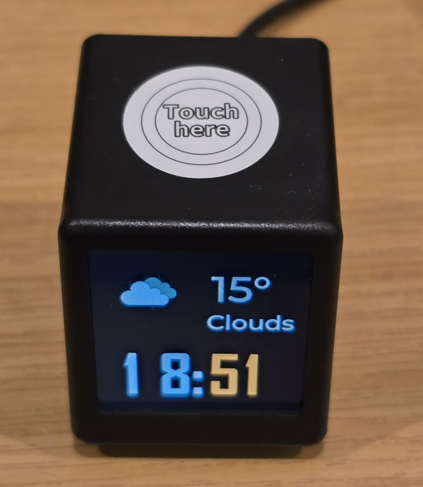
| MCU | classic ESP32, 8 MB flash |
| Display | 1.54” 240×240 IPS ST7789V, SPI, RGB colour order |
| Extras | capacitive touch button (GPIO 32, unused by this firmware) |
| WireGuard VPN | included |
| Build env | smalltv_esp32_8mb |
GeekMagic’s own higher-end model. Same cube and panel, but a classic ESP32 with 8 MB flash, which doubles the OTA app slots (2.125 MB each) and leaves about 3.7 MB for LittleFS. The partition layout matches the stock firmware’s, verified from a live device.
Unlike the ESP32-C2 board there is no USB-serial chip: the USB-C port is power only. The first install goes over the air from the stock web UI, and serial access means opening the case and wiring a 3.3 V USB-UART adapter to the internal header (see Flashing).
The pin map comes from the ESPHome SmallTV Pro community config and matches what the stock firmware uses. Confirmed working on a real device: display, colours, backlight PWM, and the 8 MB flash layout.
Pin map
Section titled “Pin map”| Signal | GPIO | Note |
|---|---|---|
| SPI CLK | 18 | |
| SPI MOSI | 23 | |
| DC | 2 | |
| RST | 4 | |
| CS | GND | tied low on the PCB, not driven |
| Backlight | 25 | PWM, active-low |
| Touch button | 32 | ESP32 T9 touch channel, unused |
The pins are set in src/board_esp32_pro.h.
If the screen looks wrong
Section titled “If the screen looks wrong”The pins are fixed to the SmallTV wiring and are not editable from the web UI. A few display symptoms have settings-level fixes:
- Dark screen with backlight on: try toggling “Backlight is active-low” in the Display tab. All boards default to active-low.
- Wrong orientation: change Orientation in the Display tab.
- Red and blue swapped: set “Colour order” to BGR in the Display tab. The board headers still carry a
TFT_BGRcompile-time default per variant, but the web UI overrides it, so there is nothing to rebuild. - Colours look warm, cold, or tinted: the panels fitted to these units are not all the same part. Use the Red, Green, and Blue gain sliders in the Display tab’s Colour card to pull the cast out.
- The screen looks like a negative: tick “Invert the panel” in the same card.
For a different board entirely, change the pins in the relevant src/board_*.h header.